GENERAL ELECTRIC, GE
INTRODUCTION
The
GE 1.5 MW wind turbines are active yaw and pitch regulated with power/torque
control capability and an asynchronous generator. The yaw system is electro-mechanically driven
with wind direction sensor and automatic cable unwinding. Power is varied using active blade pitch
control. The blade pitch angle is continually
adjusted for optimum rotational speed and maximum lift-to-drag at each wind
speed.
The variable speed operation ensures the turbines work at high efficiency, while fixed speed wind turbines only reach peak efficiency at one wind speed. While constant speed rotors must deflect high wind gust loads, the variable speed operation absorbs the loads from the gust and converts them to electric power. Cut-in and cut-out wind speeds are 3 m/s and 25 m/s respectively. The three blades give a rotor diameter of 77 m with a swept area of 4,657 m². Rotor speed is variable between 10.1 rpm and 20.4 rpm.
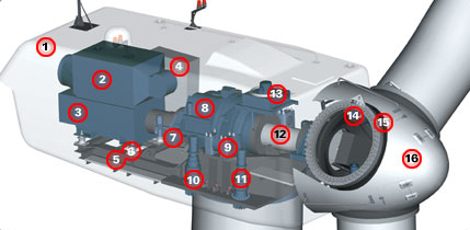
Nacelle (1), Heat Exchanger (2), Generator (3), Control Panel (4), Main Frame (5), Impact Noise Reduction (6), Hydraulic Parking Brake (7), Gearbox (8), Impact Noise Reduction (9), Yaw Drive (10 and 11), Main Shaft (12), Oil Cooler (13), Pitch Drive (14), Rotor Hub (15) and Nose Cone (16).
Fig. 1: GE 1.5 MW Wind turbine Nacelle.
OVERSPEED IN STRONG, GUSTY WINDS
Generator
torque in the turbines is controlled by the frequency converter. The turbine rotor can over speed in strong, gusty
winds to reduce torque loads in the drive train. GE's turbines store the energy in gusts by
accelerating the rotor. Operating speed
range is notably wider than the slip range used by other wind generators, which
produce heat rather than electric power when regulating power in strong, gusty
winds.
The conversion system generates reactive power or current leading voltage to improve transmission efficiencies and voltage stability, particularly useful in weak grid applications. It automatically maintains defined grid voltage levels and power quality in fractions of a second.
FAIL
The
wind generator's fail-safe braking system has electromechanical pitch control
for each blade with three self-contained systems and a hydraulic parking brake.
Lightning receptors are installed on
blade tips, with surge protection for the electrical components.
The
turbines can remain on-line and feed reactive power to the electric grid right
through major system disturbances. A Low
Voltage Ride Thru (LVRT) feature enables wind turbines to meet transmission
reliability standards similar to those demanded of thermal generators.
Active damping of the entire wind turbine system gives less tower oscillation than constant speed wind turbines. Active damping also limits peak torque, providing greater drive train reliability, reduced maintenance cost and longer turbine life. The bedplate drive train design means that all nacelle components are joined on a common structure for durability. There is a three-step planetary spur gear system, with both generator and gearbox supported by elastomeric elements to minimize noise emissions.